


;)

Cisco Appliance Light Path Diagnostics #ISE #NCS #PRIME
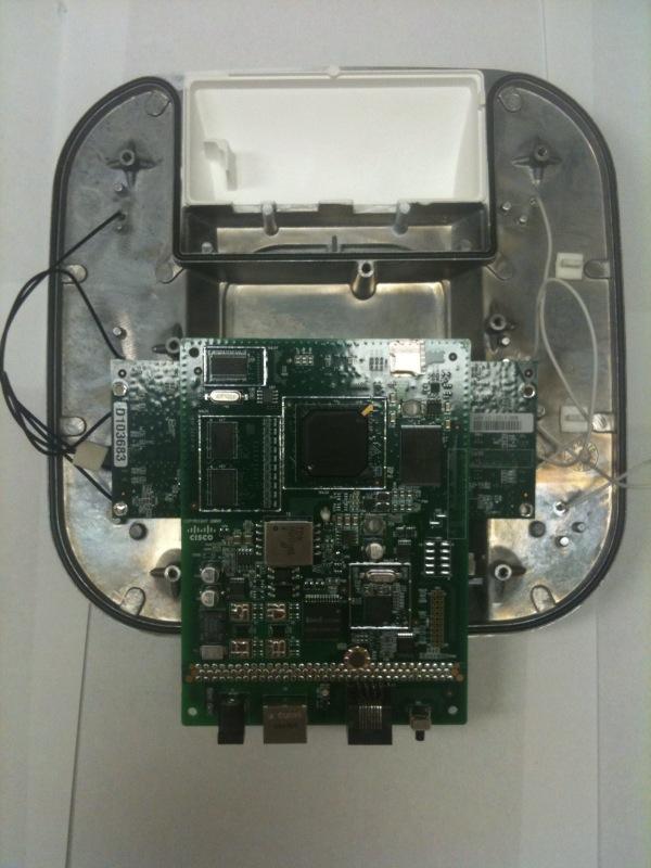
My Cisco appliance was showing the amber color exclamation point. While I did the typical show and tech commands I could not find anything wrong with the box. I checked the Light Path Diagnostics on the appliance, it quickly pointed out a power supply problem.
Figure 1-3 Light Path Diagnostics Panel
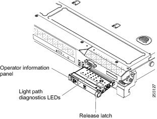
Figure 1-4 shows the LEDs and controls on the light path diagnostics panel.
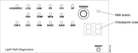
Figure 1-4 Light Path Diagnostics Panel Components
Light Path Diagnostics Panel Components
•![]() Remind button: This button places the system-error LED on the front panel into Remind mode. In Remind mode, the system-error LED flashes once every 2 seconds until the problem is corrected, the NCS appliance is restarted, or a new problem occurs.
Remind button: This button places the system-error LED on the front panel into Remind mode. In Remind mode, the system-error LED flashes once every 2 seconds until the problem is corrected, the NCS appliance is restarted, or a new problem occurs.
By placing the system-error LED indicator in Remind mode, you acknowledge that you are aware of the last failure but will not take immediate action to correct the problem.
•![]() NMI button: This button is used to force a nonmaskable interrupt to the microprocessor. This button is not currently used by the Cisco Prime Network Control System appliance. Press this button only when directed by the Cisco TAC personnel.
NMI button: This button is used to force a nonmaskable interrupt to the microprocessor. This button is not currently used by the Cisco Prime Network Control System appliance. Press this button only when directed by the Cisco TAC personnel.
•![]() Checkpoint code display: This display provides a checkpoint code that indicates the point at which the system stopped during the boot block and POST. A checkpoint code is either a byte or a word value that is produced by UEFI. The display does not provide error codes or suggest components to be replaced.
Checkpoint code display: This display provides a checkpoint code that indicates the point at which the system stopped during the boot block and POST. A checkpoint code is either a byte or a word value that is produced by UEFI. The display does not provide error codes or suggest components to be replaced.
•![]() Reset button: Press this button to reset the NCS appliance and run the power-on self-test (POST). You might have to use a pen or the end of a straightened paper clip to press the button. The Reset button is in the lower-right corner of the light path diagnostics panel.
Reset button: Press this button to reset the NCS appliance and run the power-on self-test (POST). You might have to use a pen or the end of a straightened paper clip to press the button. The Reset button is in the lower-right corner of the light path diagnostics panel.
|
Follow the suggested actions in the order in which they are listed in the Action column until the problem is solved.
|
||
|---|---|---|
|
LED
|
Description
|
Action
|
|
None, but the system error LED is lit. |
An error occurred and cannot be isolated. The error is not represented by a path. |
Contact Cisco TAC for assistance. |
|
OVER SPEC |
The power supplies are using more power than their maximum rating. |
Contact Cisco TAC for assistance. |
|
LOG |
An error occurred. |
Contact Cisco TAC for assistance. |
|
LINK |
Reserved. |
- |
|
PS |
Power supply 1 or 2 has failed. |
1. 2. 3. 4. |
|
PCI |
An error has occurred on a PCI bus or on the system board. An additional LED is lit next to a failing PCI slot. |
Contact Cisco TAC for assistance. |
|
SP |
A service processor error has been detected. |
1. 2. |
|
FAN |
A fan has failed, is operating too slowly, or has been removed. The TEMP LED might also be lit. |
Contact Cisco TAC to replace your Cisco Prime Network Control System appliance and for further assistance. |
|
TEMP |
The system temperature has exceeded a threshold level. A failing fan can cause the TEMP LED to be lit. |
Contact Cisco TAC for assistance. |
|
MEM |
When only the MEM LED is lit, a memory error has occurred. When both the MEM and CNFG LEDs are lit, the memory configuration is invalid or the PCI Option ROM is out of resource. |
Contact Cisco TAC for assistance. |
|
NMI |
A nonmaskable interrupt has occurred, or the NMI button was pressed. |
Check the system-error log for information about the error. Contact Cisco TAC if further assistance is needed. |
|
CNFG |
A hardware configuration error has occurred. |
Contact Cisco TAC for assistance. |
|
CPU |
An invalid microprocessor configuration or a microprocessor has failed (both the CPU LED and the CNFG LED might be lit). |
Contact Cisco TAC for assistance. |
|
VRM |
Reserved. |
- |
|
DASD |
A hard disk drive has failed or is missing. |
1. 2. |
|
RAID |
Reserved. |
- |
|
BRD |
An error has occurred on the system board. |
Contact Cisco TAC for assistance. |
 George