It’s that time of year and our Cisco WLC Web Authentication Certificate is close to expiration. Certificates are not my strong point and its not often I have to deal with them outside of ACS and the controllers. So I wanted to document these steps for my benefit for next go around.
This is a step by step “how to” creating a CSR (Certificate Signing Request) with OPENSSL, processing a third-party certificate that is CHAINED and download it to the Cisco WLC.
Dependency Homework
Its always important to check your dependencies and NEVER assume.
1) WLC versions earlier than 5.1.151.0, web authentication certificates can be only device certificates and DO NOT support chained certificates, ONLY ROOT SIGNED certificates
2) WLC versions 5.1.151.0 and later support chained certificates (up to a level of 2)
3) ** Certificate Levels **
Level 0 – Use of only a server certificate on WLC
Level 1 – Use of server certificate on WLC and a CA root certificate
Level 2 – Use of server certificate on WLC, one single CA intermediate certificate, and a CA root certificate.
Level 3 - Use of server certificate on WLC, two CA intermediate certificate, and a CA root certificate.
4) Entrust does not support root signed certificates (unchained) as of 12/31/2010. Since my anchors are on 4.2.x, looks like I will be upgrading my controller code.
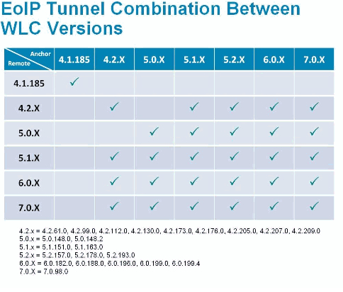
5) When anchoring, the remote and anchor controllers connect using EoIP tunnels. Below is a quick look at supported code levels . Although, Cisco will tell you its best practice to have your Anchors and Remote WLCs on the same version of code.
Why a signed certificate on the Cisco Anchor WLC?
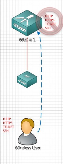
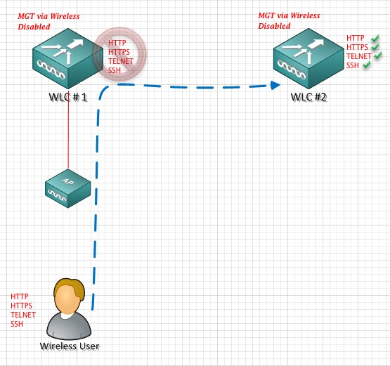
The Anchor WLC is configured with HTTPS. When a guest user connects to the wireless guest network they will be presented with a WLC self signed certificate or an expired certificate. As such, this will cause the “please accept” this certificate screen.
By installed a signed CA certificate, you negate this screen and users move directly to the accept screen. Its really a inconvenience to the end user.
OPENSSL
If this is your first time using OPENSSL, it could be a little intimidating, but it isn’t really as bad as you think. Everything is scripted.
Before starting, you will need to download and unzip OPENSSL. You will notice a number of versions. I used windows version ,0.9.8.a to create my CSR. I unzipped OPENSSL in a folder off my C: drive
C:\openssl>
http://www.openssl.org/
Generate a CSR
A CSR stands for certificate signing request. This is the first step in the certificate process.
After you have OPENSSL installed you want to launch openssl.exe. You then enter the following script.
1) C:\openssl\bin>openssl.exe
OpenSSL> req –new –newkey rsa:2048 –nodes –keyout mykey.pem –out myreq.pem
Note: The WLC supports a maximum key size of 2048
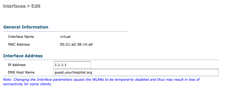
2) You will be presented with a number of questions. Your company name, state, country, common name etc. Its important to enter this information correctly. This data gets checked against the CA information on file. It is also important the CN (common name) matches the DNS A record for your virtual IP.
You will also be prompted to enter an optional password. This is important, as it adds an extra layer of security and prevents someone compiling the certificate without the password.
OpenSSL>req −new −newkey rsa:2048 −nodes −keyout mykey.pem −out myreq.pem
Loading 'screen' into random state − done Generating a 2048 bit RSA private key ................................................................++++++ ...................................................++++++
writing new private key to 'mykey.pem'
−−−−−
You are about to be asked to enter information that will be incorporated into your certificate request.
What you are about to enter is what is called a Distinguished Name or a DN. There are quite a few fields but you can leave some blank
For some fields there will be a default value, If you enter '.', the field will be left blank.
−−−−−
Country Name (2 letter code) [AU]:US
State or Province Name (full name) [Some−State]:TX
Locality Name (eg, city) []:Houston
Organization Name (eg, company) [Internet Widgits Pty Ltd]:Mycompany
Organizational Unit Name (eg, section) []:IT
Common Name (eg, YOUR name) []:guest.yourhospital.org
Email Address []:it@mycompany.com
Please enter the following 'extra' attributes to be sent with your certificate request
A challenge password []:TESTEST
An optional company name []:
OpenSSL>
3) Once you are complete. You will find 2 files in the bin folder.
- mykey.pem
- myreq.pem
The mykey.pem is your portion of the CSR which will be used later. Keep this in a safe place.
The myreq.pem is your CSR ,which is sent to your CA. If you change the file type from .pem to .txt you will see something similar to this:
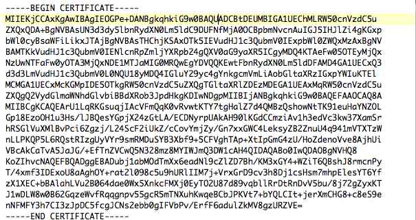
4) The CA will reply with a digitally signed certificate chain. You will receive three certificates.
- Root Certificate
- Intermediate Certificate
- Device Certificate
5) The next step, you will want to take the 3 certificates and change the extension to .txt.
Entrust.cer
L1Cchainroot.cer
L1Croot.cer
Once the extensions are converted to .txt. Open notepad and cut and paste the certificates in this order:
−−−−−−BEGIN CERTIFICATE−−−−−−
*Device cert*
−−−−−−END CERTIFICATE−−−−−−
−−−−−−BEGIN CERTIFICATE−−−−−−
*Intermediate CA cert *
−−−−−−END CERTIFICATE−−−−−−−−
−−−−−−BEGIN CERTIFICATE−−−−−−
*Root CA cert *
−−−−−−END CERTIFICATE−−−−−−
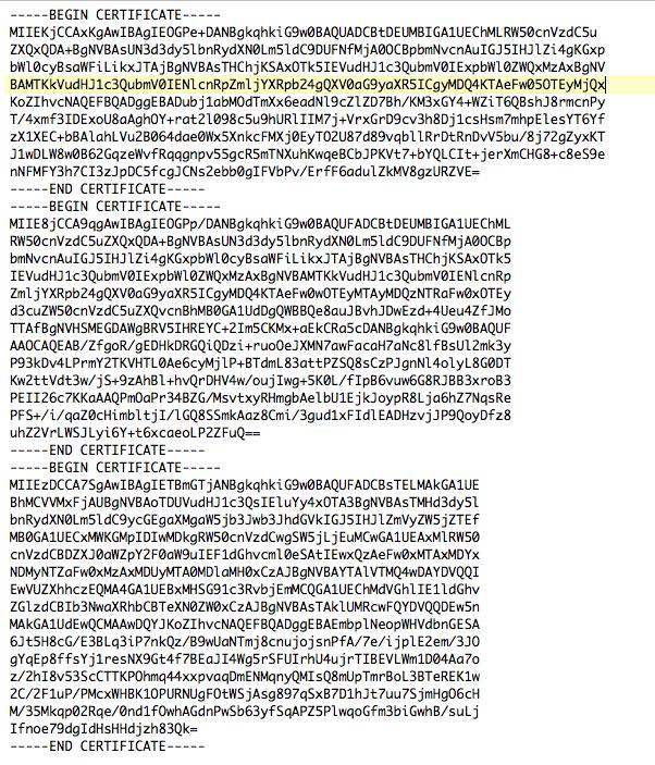 **NOTE THESE ARE NOT REAL CERTIFICATES**
It is important you put the certs in the correct order -- device, intermediate, root.
- Device Certificate
- Intermediate Certificate
- Root Certificate
Specific to Entrust … your cert order would be the following:
- Device Certificate ------------------ L1Croot
- Intermediate Certificate-----------L1Cchainroot
- Root Certificate----------------------Entrust
**NOTE IF YOU OPEN THE ROOT CERTIFICATE THIS WILL CONTAIN YOUR CN (COMMON NAME) **
6) Save the file as All-certs.pem
7) In this step you will combine your mykey.pem and the All-certs.pem. Open up OPENSLL again. Enter the following:
C:\openssl\bin>openssl.exe
OpenSSL> pkcs12 -export -in All-certs.pem -inkey mykey.pem -out All-certs.p12 -clcerts -passin pass:TESTTEST -passout pass:TESTTEST
Loading 'screen' into random state - done
OpenSSL> pkcs12 -in All-certs.p12 -out final-cert.pem -passin pass:TESTTEST -passout pass:TESTTEST
MAC verified OK
OpenSSL>
**NOTE YOU ENTER THE PASSWORD YOU CREATED DURING THE CSR CREATION **
8) When you are done you will have 1 file, called final-cert.pem. This is the certificate you will download to your Anchor WLC.
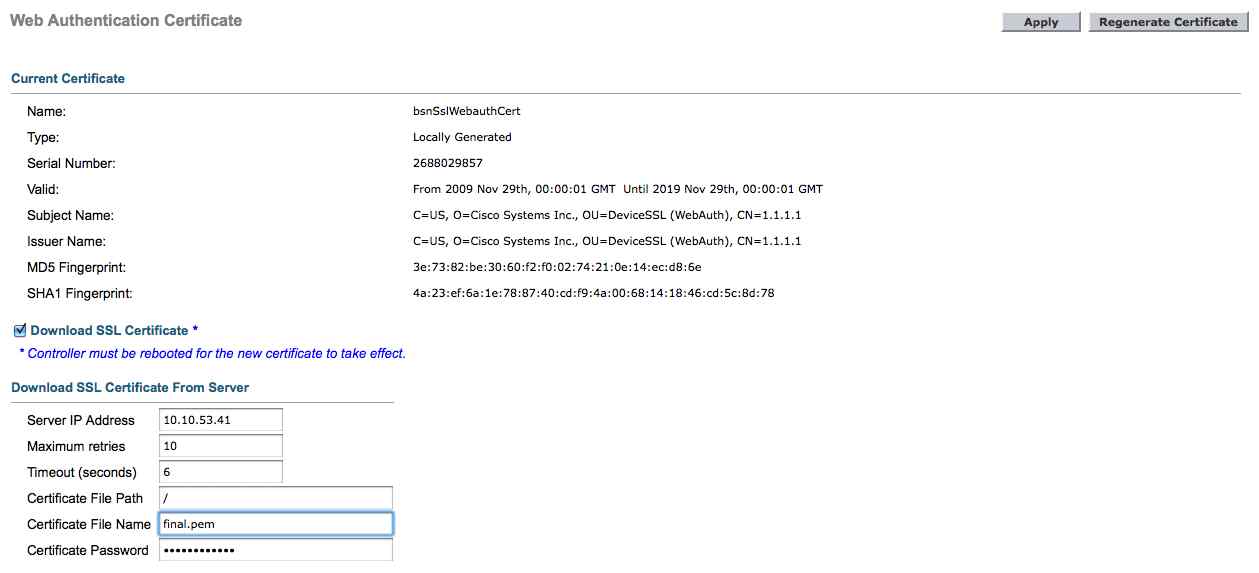
9) Enter your WLC Security ->Web Auth -> Certificate
Check, check box “Download SSL Certifciate” and enter your TFTP information and your certificate password.


;)


 George