INTEL WIRELESS
Wired Stuff
WiFi Tablet Corner
My80211 White Papers (Coming Soon!)

Cisco Wireless Compatibility Matrix (Nov. 2011)

Podcasts / Videos

My80211 Videos

Cisco: 802 11 frames with Cisco VIP George Stefanick

Fluke Networks: Minimize Wi Fi Network Downtime

Aruba: Packets never lie: An in-depth overview of 802.11 frames

ATM15 Ten Talk “Wifi drivers and devices”

Houston Methodist Innovates with Wireless Technology

Bruce Frederick Antennas (1/2)


Bruce Frederick dB,dBi,dBd (2/2)

Cisco AP Group Nugget

Social Links
Revolution WiFi Capacity Planner

Anchor / Office Extends Ports


Peek Inside Cisco's Gear

See inside Cisco's latest wireless gear!

2.4 GHz Channel Overlap

EXAMPLE 1  

EXAMPLE 2

EXAMPLE 3  

CWSP RELEASE DATE 2/08/2010
  • CWSP Certified Wireless Security Professional Official Study Guide: Exam PW0-204
    CWSP Certified Wireless Security Professional Official Study Guide: Exam PW0-204
    by David D. Coleman, David A. Westcott, Bryan E. Harkins, Shawn M. Jackman

    Shawn Jackman (Jack) CWNE#54 is a personal friend and has been a mentor to me for many years.  I've had the pleasure and opportunity to work with Jack for 4 years. Jack is a great teacher who takes complex 802.11 standards and breaks them down so almost anyone can understand the concept at hand. I'm excited for you brother. Great job and job well done! Put another notch in the belt!

IEEE 802.11a/g/n Reference Sheet


LWAPP QoS Packet Tagging


Interference Types

BLUETOOTH
 

Microwave Oven
 

Cordless Phone

JAMMER!


Wednesday
Feb022011

Cisco Wireless Solutions Software Compatibility Matrix

Updated Wireless Matrix, December 2010 for WCS, WLC, Mesh and more !

This is a "must check" for your dependencies prior to upgrading.

December 2010

This document describes the software compatibility matrix for the Cisco wireless devices used in a Cisco Centralized and Distributed WLAN Solution.

  • Software Release Compatibility Matrix
  • Mesh and Mainstream Controller Software Releases
  • Wireless Control System Compatibility Matrix
  • Inter-Release Controller Mobility (IRCM)

Cisco Wireless Solutions Software Compatibility Matrix PDF download


Wednesday
Jan192011

Guest Access with Mobility Anchor Chalk Talk 

If you are new to Cisco Guest Access with Anchor controllers this is a good video to get the fundamentals down.

This video walks you through the anchor process. It also includes decodes which are boken down step by step.

https://supportforums.cisco.com/videos/1212

Sample:

(Cisco Controller) >

(Cisco Controller) >

(Cisco Controller) >Sat Sep 27 10:45:15 2008: dhcpd: Received 300 byte dhcp packet from 0xc0a80019 192.168.0.25:68

Sat Sep 27 10:45:20 2008: dhcpd: Received 300 byte dhcp packet from 0xc0a80019 192.168.0.25:68

Sat Sep 27 10:45:39 2008: 00:0e:35:f3:60:53 Adding mobile on Remote AP 00:00:00:00:00:00(0)

The anchor controller is informed of the association request from the client by the foreign controller. However, the anchor is not aware of the AP to which the client is associating, since the L1 and L2 parts of the connection are managed by the foreign controller.

Sat Sep 27 10:45:39 2008: 00:0e:35:f3:60:53 0.0.0.0 START (0) Initializing policy

Sat Sep 27 10:45:39 2008: 00:0e:35:f3:60:53 0.0.0.0 START (0) Change state to AUTHCHECK (2) last state AUTHCHECK (2)

Sat Sep 27 10:45:39 2008: 00:0e:35:f3:60:53 0.0.0.0 AUTHCHECK (2) Change state to L2AUTHCOMPLETE (4) last state L2AUTHCOMPLETE (4)

Sat Sep 27 10:45:39 2008: 00:0e:35:f3:60:53 0.0.0.0 L2AUTHCOMPLETE (4) Change state to DHCP_REQD (7) last state DHCP_REQD (7)

Sat Sep 27 10:45:39 2008: 00:0e:35:f3:60:53 Stopping deletion of Mobile Station: (callerId: 53)

Sat Sep 27 10:45:39 2008: 00:0e:35:f3:60:53 0.0.0.0 DHCP_REQD (7) State Update from Mobility-Incomplete to Mobility-Complete, mobility role=ExpAnchor

Sat Sep 27 10:45:39 2008: 00:0e:35:f3:60:53 0.0.0.0 DHCP_REQD (7) Change state to DHCP_REQD (7) last state DHCP_REQD (7)

Sat Sep 27 10:45:39 2008: 00:0e:35:f3:60:53 0.0.0.0 DHCP_REQD (7) pemAdvanceState2 3949, Adding TMP rule

Sat Sep 27 10:45:39 2008: 00:0e:35:f3:60:53 0.0.0.0 DHCP_REQD (7) Adding Fast Path rule

  type = Airespace AP - Learn IP address

  on AP 00:00:00:00:00:00, slot 0, interface = 1, QOS = 0

  ACL Id = 255, Jumbo Frames = NO, 802.1P = 0, DSCP = 0, TokenID = 5006

Sat Sep 27 10:45:39 2008: 00:0e:35:f3:60:53 0.0.0.0 DHCP_REQD (7) Successfully plumbed mobile rule (ACL ID 255)

Sat Sep 27 10:45:39 2008: 00:0e:35:f3:60:53 Set bi-dir guest tunnel for 00:0e:35:f3:60:53 as in Export Anchor role

The anchor controller is being informed that the client passed the L2 authentication and that, after successful association, it is now going into the DHCP_REQD state.

Also, the controller is updating its status to be the Export Anchor for this client.

Sat Sep 27 10:45:39 2008: 00:0e:35:f3:60:53 0.0.0.0 Added NPU entry of type 9

The client entry is added to the Network Processing Unit (NPU) of the controller with an IP address of 0.0.0.0: this means that the client is successfully associated, but it does not have an IP address yet.

Sat Sep 27 10:45:39 2008: 00:0e:35:f3:60:53 Sent an XID frame

Sat Sep 27 10:45:41 2008: 00:0e:35:f3:60:53 DHCP received op BOOTREQUEST (1) (len 308, port 1, encap 0xec00)

Sat Sep 27 10:45:41 2008: 00:0e:35:f3:60:53 DHCP option len (including the magic cookie) 72

Sat Sep 27 10:45:41 2008: 00:0e:35:f3:60:53 DHCP option: message type = DHCP DISCOVER

Sat Sep 27 10:45:41 2008: 00:0e:35:f3:60:53 DHCP option: 116 (len 1) - skipping

Sat Sep 27 10:45:41 2008: 00:0e:35:f3:60:53 DHCP option: 61 (len 7) - skipping

Sat Sep 27 10:45:41 2008: 00:0e:35:f3:60:53 DHCP option: 12 (len 7) - skipping

Sat Sep 27 10:45:41 2008: 00:0e:35:f3:60:53 DHCP option: vendor class id = MSFT 5.0 (len 8)

Sat Sep 27 10:45:41 2008: 00:0e:35:f3:60:53 DHCP option: 55 (len 11) - skipping

Sat Sep 27 10:45:41 2008: 00:0e:35:f3:60:53 DHCP options end, len 72, actual 64

Sat Sep 27 10:45:41 2008: 00:0e:35:f3:60:53 DHCP selecting relay 1 - control block settings:

                        dhcpServer: 0.0.0.0, dhcpNetmask: 0.0.0.0,

                        dhcpGateway: 0.0.0.0, dhcpRelay: 0.0.0.0  VLAN: 0

Sat Sep 27 10:45:41 2008: 00:0e:35:f3:60:53 DHCP selected relay 1 - 192.168.51.1 (local address 192.168.51.203, gateway 192.168.51.1, VLAN 601, port 1)

Sat Sep 27 10:45:41 2008: 00:0e:35:f3:60:53 DHCP transmitting DHCP DISCOVER (1)

Sat Sep 27 10:45:41 2008: 00:0e:35:f3:60:53 DHCP   op: BOOTREQUEST, htype: Ethernet, hlen: 6, hops: 1

Sat Sep 27 10:45:41 2008: 00:0e:35:f3:60:53 DHCP   xid: 0xd5771135 (3581350197), secs: 0, flags: 0

Sat Sep 27 10:45:41 2008: 00:0e:35:f3:60:53 DHCP   chaddr: 00:0e:35:f3:60:53

Sat Sep 27 10:45:41 2008: 00:0e:35:f3:60:53 DHCP   ciaddr: 0.0.0.0,  yiaddr: 0.0.0.0

Sat Sep 27 10:45:41 2008: 00:0e:35:f3:60:53 DHCP   siaddr: 0.0.0.0,  giaddr: 192.168.51.203


Wednesday
Jan192011

Cisco Releases iPhone APP v1.0 for CSC (Cisco Support Community)

If you follow CSC and have an iPhone you are in luck my friend!

Cisco Support Community is a great forum and I always point folks to CSC when they have issues or if they are new to Cisco networking and want to learn.

Cisco released an iPhone app called “Cisco Technical Support”, which can be found in iTunes. I’ve used it for the first time today and I like it a lot. It keeps you connected to the forums easily.

Kudos to Dan and the other Cisco guys for making this happen!

https://supportforums.cisco.com/docs/DOC-13891


Sunday
Jan162011

WLC:Generate Third Party Web Authentication Certificate for a WLC

It’s that time of year and our Cisco WLC Web Authentication Certificate is close to expiration. Certificates are not my strong point and its not often I have to deal with them outside of ACS and the controllers. So I wanted to document these steps for my benefit for next go around.

This is a step by step “how to” creating a CSR (Certificate Signing Request) with OPENSSL, processing a third-party certificate that is CHAINED and download it to the Cisco WLC.

Dependency Homework

Its always important to check your dependencies and NEVER assume.

1) WLC versions earlier than 5.1.151.0, web authentication certificates can be only device certificates and DO NOT support chained certificates, ONLY ROOT SIGNED certificates

2) WLC versions 5.1.151.0 and later support chained certificates (up to a level of 2)

3)   ** Certificate Levels **

Level 0 – Use of only a server certificate on WLC
Level 1 – Use of server certificate on WLC and a CA root certificate
Level 2 – Use of server certificate on WLC, one single CA intermediate certificate, and a CA root certificate.
Level 3 -  Use of server certificate on WLC, two CA intermediate certificate, and a CA root certificate. 

4) Entrust does not support root signed certificates (unchained) as of 12/31/2010. Since my anchors are on 4.2.x, looks like I will be upgrading my controller code.

5) When anchoring, the remote and anchor controllers connect using EoIP tunnels. Below is a quick look at supported code levels . Although, Cisco will tell you its best practice to have your Anchors and Remote WLCs on the same version of code.


Why a signed certificate on the Cisco Anchor WLC?

The Anchor WLC is configured with HTTPS. When a guest user connects to the wireless guest network they will be presented with a WLC self signed certificate or an expired certificate. As such, this will cause the “please accept” this certificate screen.

By installed a signed CA certificate, you negate this screen and users move directly to the accept screen. Its really a inconvenience to the end user.

OPENSSL

If this is your first time using OPENSSL, it could be a little intimidating, but it isn’t really as bad as you think. Everything is scripted.

Before starting, you will need to download and unzip OPENSSL. You will notice a number of versions. I used windows version ,0.9.8.a to create my CSR.  I unzipped OPENSSL in a folder off my C: drive

C:\openssl>

http://www.openssl.org/

Generate a CSR

A CSR stands for certificate signing request. This is the first step in the certificate process.

After you have OPENSSL installed you want to launch openssl.exe. You then enter the following script.

1)   C:\openssl\bin>openssl.exe

OpenSSL> req –new –newkey rsa:2048 –nodes –keyout mykey.pem –out myreq.pem
Note: The WLC supports a maximum key size of 2048

2)   You will be presented with a number of questions. Your company name, state, country, common name etc. Its important to enter this information correctly. This data gets checked against the CA information on file. It is also important the CN (common name) matches the DNS A record for your virtual IP.


You will also be prompted to enter an optional password. This is important, as it adds an extra layer of security and prevents someone compiling the certificate without the password.

OpenSSL>req −new −newkey rsa:2048 −nodes −keyout mykey.pem −out myreq.pem

Loading 'screen' into random state − done Generating a 2048 bit RSA private key ................................................................++++++ ...................................................++++++

writing new private key to 'mykey.pem'
−−−−−
You are about to be asked to enter information that will be incorporated into your certificate request.

What you are about to enter is what is called a Distinguished Name or a DN. There are quite a few fields but you can leave some blank

For some fields there will be a default value, If you enter '.', the field will be left blank.
−−−−−
Country Name (2 letter code) [AU]:US
State or Province Name (full name) [Some−State]:TX
Locality Name (eg, city) []:Houston
Organization Name (eg, company) [Internet Widgits Pty Ltd]:Mycompany
Organizational Unit Name (eg, section) []:IT
Common Name (eg, YOUR name) []:guest.yourhospital.org
Email Address []:it@mycompany.com

Please enter the following 'extra' attributes to be sent with your certificate request

A challenge password []:TESTEST
An optional company name []:

OpenSSL>

 3)   Once you are complete. You will find 2 files in the bin folder.

  1. mykey.pem
  2. myreq.pem

The mykey.pem is your portion of the CSR which will be used later. Keep this in a safe place.

The myreq.pem is your CSR ,which is sent to your CA. If you change the file type from .pem to .txt you will see something similar to this:


4) The CA will reply with a digitally signed certificate chain. You will receive three certificates.

  1. Root Certificate
  2. Intermediate Certificate
  3. Device Certificate

5)   The next step, you will want to take the 3 certificates and change the extension to .txt.

Entrust.cer
L1Cchainroot.cer
L1Croot.cer

Once the extensions are converted to .txt. Open notepad and cut and paste the certificates in this order:

−−−−−−BEGIN CERTIFICATE−−−−−−
*Device cert*
−−−−−−END CERTIFICATE−−−−−−
−−−−−−BEGIN CERTIFICATE−−−−−−
*Intermediate CA cert *
−−−−−−END CERTIFICATE−−−−−−−−
−−−−−−BEGIN CERTIFICATE−−−−−−
*Root CA cert *
−−−−−−END CERTIFICATE−−−−−−

 **NOTE THESE ARE NOT REAL CERTIFICATES**

 It is important you put the certs in the correct order -- device, intermediate, root.

  1. Device Certificate
  2. Intermediate Certificate
  3. Root Certificate

 Specific to Entrust … your cert order would be the following:

  1. Device Certificate ------------------ L1Croot
  2. Intermediate Certificate-----------L1Cchainroot
  3. Root Certificate----------------------Entrust

 **NOTE IF YOU OPEN THE ROOT CERTIFICATE THIS WILL CONTAIN YOUR CN (COMMON NAME) **

 6)   Save the file as All-certs.pem

 7)   In this step you will combine your mykey.pem and the All-certs.pem. Open up OPENSLL again. Enter the following:

C:\openssl\bin>openssl.exe

OpenSSL> pkcs12 -export -in All-certs.pem -inkey mykey.pem -out All-certs.p12 -clcerts -passin pass:TESTTEST -passout pass:TESTTEST

Loading 'screen' into random state - done

OpenSSL> pkcs12 -in All-certs.p12 -out final-cert.pem -passin pass:TESTTEST -passout pass:TESTTEST

MAC verified OK

OpenSSL>

**NOTE YOU ENTER THE PASSWORD YOU CREATED DURING THE CSR CREATION **

8)   When you are done you will have 1 file, called final-cert.pem. This is the certificate you will download to your Anchor WLC.

9) Enter your WLC Security ->Web Auth -> Certificate

Check, check box “Download SSL Certifciate” and enter your TFTP information and your certificate password.


Monday
Jan032011

Firefox and WLC Certificate Issues

Have you tried to log into a Cisco WLC with Firefox and get an annoying certificate conflict message? No worries you can fix it !

Firefox collects certificates and will compare incoming certificates. If these certificates match but come from different sources Firefoxs throws the annoying certificate conflict message.

The HTTPS certificate on the WLC lives at MANAGEMENT-->HTTP-->CURRENT CERTIFICATE

Where the problem arrives, controllers shipped in batches appear to have the same identical certificates. This could be because they “blast” the firmware on the boxes in the manufacturing process.

An example of a factory provided certificate is below. First noticed there is no CN information and the validation date is way off.  This same certificate was on all the controllers in the batch.

The first controller you log into Firefox would accept and store this certificate. However, any controller you attempted to log into afterward would receive a certificate conflict.


So, how do we fix this issue? It's very simple …

After you configure your WLC with an IP address. Simply go to MANAGEMENT-->HTTP and click on regenerate certificate.  It will fill in a proper validation date and more specific CN information giving the certificate its true identity. However, this does require a controller reboot. So schedule accordingly. Below is a regenerated certificate.


Thats it! It should work now! Enjoy ....

Friday
Dec242010

ASK THE EXPERTS: Cisco Clean Air (Cisco Support Community)

Cisco Clean Air with Nicolas Darchis and Federico Ziliotto

Learn about the last generation of access points from Cisco and the integration of the Clean Air technology to locate and mitigate interferences.
Starts January 3, 2011

https://supportforums.cisco.com/community/netpro/ask-the-expert

Tuesday
Dec142010

End-of-Sale and End-of-Life Announcement for the Cisco Catalyst 3750 Series Integrated Wireless LAN Controllers

Title: End-of-Sale and End-of-Life Announcement for the Cisco Catalyst 3750 Series Integrated Wireless LAN Controllers

Description: Cisco announces the end-of-sale and end-of life dates for the Cisco Catalyst 3750 Series Integrated Wireless LAN Controllers. The last day to order the affected product(s) is June 13, 2011. Customers with active service contracts will continue to receive support from the Cisco Technical Assistance Center (TAC) as shown in Table 1 of the EoL bulletin.

Table 1 describes the end-of-life milestones, definitions, and dates for the affected product(s). Table 2 lists the product part numbers affected by this announcement. For customers with active and paid service and support contracts, support will be available until the termination date of the contract, even if this date exceeds the Last Date of Support shown in Table 1.
Date: 2010-12-13 09:00:00.0

http://www.cisco.com/en/US/prod/collateral/wireless/ps6302/ps7185/ps6915/end_of_life_notice_c51-634675.html

Tuesday
Dec142010

End-of-Sale and End-of-Life Announcement for the Cisco 4400 Series Wireless LAN Controllers

Here is the official announcement from Cisco on the EOS / EOL of the Cisco 4400 controller

Title: End-of-Sale and End-of-Life Announcement for the Cisco 4400 Series Wireless LAN Controllers

Description: Cisco announces the end-of-sale and end-of life dates for the Cisco 4400 Series Wireless LAN Controllers.

The last day to order the affected product(s) is June 13, 2011. Customers with active service contracts will continue to receive support from the Cisco Technical Assistance Center (TAC) as shown in Table 1 of the EoL bulletin. Table 1 describes the end-of-life milestones, definitions, and dates for the affected product(s). Table 2 lists the product part numbers affected by this announcement.

For customers with active and paid service and support contracts, support will be available until the termination date of the contract, even if this date exceeds the Last Date of Support shown in Table 1.
Date: 2010-12-13 09:00:00.0


http://www.cisco.com/en/US/prod/collateral/wireless/ps6302/ps8322/ps6366/end_of_life_notice_c51-634665.html

Sunday
Oct312010

Cisco - "Don't forget spectrum" - DFS Testing

Cisco's short video on DFS and their wireless controller solution. Its a quick video on DFS and client capacity testing taking advantage of DFS UNII-2 Extended. 

 They also take a poke @ Aruba in the process... :P

Saturday
Oct232010

PoE Power Switches (Midspans) – Inexpensive Power Management Alternative

As a consultant, customer budgets are almost always KING. Sometimes PoE switches aren’t in the budget for the WLAN deployment. So what options do you have? 

Managed power switches, also called “midspans” have been around for a longtime. In fact they are thecost alternative to PoE switches. A Cisco PoE switch will set you back some heavy green, especially if it’s enhanced power, 802.3at. Also, customers don’t like the mess of power injectors and the lack of management. You can’t easily power cycle an access point that is hooked to an injector, which means a certain visit to the IDF closet.  

Over the years, I’ve worked with and deployed projects with PoE Power Switches / midspans. These are simple data pass through devices, similar to PoE injectors. The difference is these come in small 6 to 48 ports, 1u switches. Also, certain models are managed, which means you log into the Power Switch and simply power cycle the port.

There are a number of vendors and options when selecting a power switch. Personally, I've used and deployed Microsemi PowerDsine in a number of accounts. I also use a 9000G in my home lab.

PowerDsine has a real nice product line with a number of models and options.  They start off with the simple 1 port PoE injector to a PoE extender that pushes power and data to 200 meters! PowerDsine models provide 802.3at and 802.3af power. They also provide a Cisco “Splitter” for devices that are only Cisco PoE compatible.

These also come in handy when you need to stage a large deployment and prime your access points.

http://www.microsemi.com/powerdsine/Products/Midspan/

Thursday
Oct212010

WLC: Schedule Reboot of the WLC from the CLI

Did you know you can schedule a reboot of the WLC in the CLI? This comes in handy if you don’t have a WCS. Lets cover the different automatic reboots . Also this is only in newer code releases. This is not an option in 4.2 releases.

(Cisco_4402_WLC) >reset system ?
at             Reset the system at a specified time.
in             Reset the system after a specified delay.
cancel         Cancel a scheduled reset.
notify-time    Configures trap generation prior to scheduled resets.

Reset System In ->

The (rest system in) command allows you to enter a specific time to have the controller reboot. Also you can call out what image (primary / backup) to load.

(Cisco_4402_WLC) >reset system in 00:01:30 image no-swap reset-aps save-config
System reset is scheduled for Oct 16 22:58:56 2010.
Current local time and date is Oct 16 22:57:26 2010.
Trap will not be generated as total delay is less than the trap time.
Use 'reset system cancel' to cancel the reset.
Configuration will be saved before the system reset.
(Cisco_4402_WLC) >


Rest System At ->

The (rest system at) command allows you to enter a specific date and time to have the controller reboot.  Like reset system in, you can call out the image as well.

 (Cisco_4402_WLC) >reset system at 2010-10-16 23:05:00 image no-swap reset-aps save-config
System reset is scheduled for Oct 16 23:05:00 2010.
Current local time and date is Oct 16 23:02:06 2010.
Trap will not be generated as total delay is less than the trap time.
Use 'reset system cancel' to cancel the reset.
Configuration will be saved before the system reset.
(Cisco_4402_WLC) >


Reset System Cancel ->

Of course, if you scheduled a system reset and you need to cancel it. You would need to apply the reset system cancel command

(Cisco_4402_WLC) >reset system ?
at             Reset the system at a specified time.
in             Reset the system after a specified delay.
cancel         Cancel a scheduled reset.
notify-time    Configures trap generation prior to scheduled resets.


Show Reset ->

To double check your schedule reset you can do the “show rest” command. It outlines the data and events.

(Cisco_4402_WLC) >show reset
System reset is scheduled for Oct 18 10:00:00 2010.
Current local time and date is Oct 16 23:28:15 2010.
All APs will also be reset.
A trap will be generated 10 minutes before each scheduled system reset.
Configuration will be saved before the system reset.


Tuesday
Oct192010

IPAD OTTERBOX REVIEW

After trial and error with countless  iPAD cases. The OtterBox Defender is a winner for me!

Since the purchase of my iPad a number of months ago. I’ve been testing a number of cases. I found that most cases offer little or no drop protection and the fit for most cases were OK, but not perfect.

 As an active engineer, who is one day in the office and the next day on a construction site.  I needed a case that was rugged, but yet usable and practical. Since I was already a satisfied OtterBox customer with my eariler purchase of the iPhone OtterBox. I eagerly awaited the release of the iPad cases.

OtterBox has two iPAD case offerings. They’re called the Defender and the Commuter.  After a close inspection of both cases, the Defender was my choice because of its rugged protection. 

After a few weeks of using the Defender I have to say, I am very satisfied with the OtterBox Defender case and I would recommend it.

The case is made of durable plastic with a rubber overlay that fits over the back and sides of the iPAD in typical OtterBox fashion. The iPAD power adapter section of the case slides off which allows access to the plug section. I really like this because it protects elements from getting in the adapter connection while in the field.

The side volume buttons are a perfect fit and work well. The other “ports” like the headset jack and screen lock are well protected. Another great feature is the plastic cover which also converts into an iPad desk stand. The cover fits nice over the case which protects the screen from direct hits when not in use. Also, the case adds a little weight to the iPad and its noticeable. Which I like actually.

As for drop testing. My iPad and the ground have been introduced a few times by accident. The OtterBox clearly protected my investment. The only draw back, is the cost. These cases aren’t cheap at $90.00, but it’s worth every penny!

Defender:

Drop-proof your magical, new must-have gadget with the OtterBox Defender Series for Apple® iPad™! This cutting-edge case incorporates three layers of hardcore protection plus some advanced features. Stowing your iPad away for the night or for your commute? Simply remove the back polycarbonate cover and snap it over the face for ultimate touch screen protection. The built-in stand will come in handy while trying to watch a movie or video, and creates a comfortable browsing experience. When using your iPad on a flat surface, the silicone grip pads on the bottom will hold your device securely in place. We also designed this case to accommodate the optional iPad dock accessory! Take your iPad everywhere you go knowing that it is safe from the occasional drop, bump and/or scratch.

Commuter:

The slim and attractive OtterBox Commuter Series for Apple® iPad™ is sure to protect your new toy from everyday mishaps. Enjoy full access to all buttons, ports and features, along with snap-off access for your optional iPad dock. Also included with the case is a self-adhering protective film for your touch screen to safeguard against unsightly scratches and dings. This innovative OtterBox case will increase your peace of mind while keeping your iPad as fabulous as the day you bought it! About our Commuter Series: Three slender, yet sturdy layers offer tough protection in a sleek package. With a slim form factor and smooth outer layer, this case slides easily in and out of a pocket, purse or bag.


Tuesday
Oct192010

WLC: Debug Transfer Trace

The WLC has a wealth of debug commands. I ran into image problems in my lab this weekend.  If you run into TFTP or IMAGE transfer issues a handy debug is the debug transfer trace / tftp enable.

If you have issues contacting the TFTP server from the WLC or image mounting issues this debug will alert you as to the issue.

debug transfer trace enable

debug transfer tftp enable

Here is an example of the debug transfer trace:

(Cisco_4402_WLC) >debug transfer trace enable
*Oct 17 21:44:25.925: RESULT_STRING: TFTP Code transfer starting.
*Oct 17 21:44:25.925: RESULT_CODE:1
*Oct 17 21:44:29.928: Locking tftp semaphore, pHost=10.10.53.24 pFilename=/SWISMK9-6-0-199-4.aes
*Oct 17 21:44:29.929: Semaphore locked, now unlocking, pHost=10.10.53.24 pFilename=/SWISMK9-6-0-199-4.aes
*Oct 17 21:44:29.929: Semaphore successfully unlocked, pHost=10.10.53.24 pFilename=/SWISMK9-6-0-199-4.aes
*Oct 17 21:52:01.997: tftp rc=0, pHost=10.10.53.24 pFilename=/SWISMK9-6-0-199-4.ae pLocalFilename=/mnt/download/local.tgz
*Oct 17 21:52:01.998: tftp = 6, file_name=/SWISMK9-6-0-199-4.aes, ip_address=10.10.53.24, msg=Unknown error - refer to log
*Oct 17 21:52:01.998: upd_get_code = 6 (target=268435457 msg=Unknown error - refer to log)
*Oct 17 21:52:01.999: RESULT_STRING: TFTP receive complete... extracting components.
*Oct 17 21:52:01.999: RESULT_CODE:6
*Oct 17 21:52:07.022: RESULT_STRING: Executing Product Check TLV.
*Oct 17 21:52:07.023: RESULT_STRING: Executing init script.
*Oct 17 21:52:07.131: RESULT_STRING: Executing backup script.
*Oct 17 21:53:29.209: RESULT_STRING: Writing new RTOS to flash disk.
*Oct 17 21:53:31.577: RESULT_STRING: Writing new Code to flash disk.
*Oct 17 21:53:56.451: RESULT_STRING: Writing new APIB to flash disk.
*Oct 17 21:55:05.911: RESULT_STRING: Executing install_apib script.
*Oct 17 21:56:52.738: RESULT_STRING: Executing fini script.
*Oct 17 21:56:53.037: RESULT_STRING: TFTP File transfer is successful.
Reboot the controller for update to complete.
 Optionally, pre-download the image to APs before rebooting to reduce network downtime.
*Oct 17 21:56:53.037: RESULT_CODE:11
*Oct 17 21:56:57.039: ummounting: <umount /mnt/download/>  cwd  = /mnt/application
*Oct 17 21:56:57.077: finished umounting
(Cisco_4402_WLC) >

Sunday
Oct172010

GEORGE STEFANICK - CWSP JOURNEY, (CHAPTER 4 – EAP, EAP, EAP AND MORE EAP, POST#7)- 10/17/2010

Chapter 4 is one of my favorite chapters. Why you ask? It’s the very foundation to advance wireless security.  EAP is the process where it all begins and comes together. 

Have you ever talked to a vendor or colleague who is not familiar with EAP. You get that glazed look, as if you were from another planet? EAP is rather easy to understand once you know the structure. So lets cover the basics first. 

WHAT EAP (IS) AND (IS NOT)

EAP stands for “Extensible Authentication Protocol”. EAP is an authentication frame work that has been around for a long long time.. What EAP is NOT is an authentication mechanism. There is often confusion about this very statement. EAP doesn’t authenticate, but rather it provides the messaging system, the structure, for which authentication mechanisms like EAP-PEAP, EAP-TTLS, EAP-FAST, EAP-LEAP may operate.

EAP was developed long ago, It was used primarily in point to point authentication (PPP). Whereby clients were authenticated to a network using an EAP authentication. Today, EAP is commonly used in wireless authentication and this will be the focus of my notes.

EAP is defined in RF3748 (http://tools.ietf.org/html/rfc3748). As I just shared it is the frame work or the message systems whereby different flavors of EAP can be used.

Abstract

   This document defines the Extensible Authentication Protocol (EAP),
   an authentication framework which supports multiple authentication
   methods.  EAP typically runs directly over data link layers such as
   Point-to-Point Protocol (PPP) or IEEE 802, without requiring IP.  EAP
   provides its own support for duplicate elimination and
   retransmission, but is reliant on lower layer ordering guarantees.
   Fragmentation is not supported within EAP itself; however, individual
   EAP methods may support this.” 

.  Chapter 4 covers a rather broad range of information.

  • ·         AAA (Authentication, Authorization, Accounting)
  • ·         802.1X Process and structure
  • ·         Supplicant Credentials; types and uses
  • ·         Authentication Protocols
  • ·         EAP

My next few post will be the break down of each section …

Sunday
Oct172010

Joshua Wright talks to NPR about “Free Public WiFi” vulnerability

Joshua Wright talks briefly about the “Free Public WiFi”, adhoc network. This tactic has been around for a longtime. In fact, frequent travelers should be on the look out for hotel chain SSIDs in adhoc mode as well.

Depending on your configuration your wireless supplicant may connect automatically to these adhoc networks without you really knowing. Other times, the users sees a pop up “Free Public WiFi” and willingly connects to the network in hopes of free internet access. To the untrained eye these are wireless networks promising a free WiFi connection. However, you have no idea who is on the other end. The mobile user suspects it a real access point.

This NPR article stops by saying “it’s a bad thing and you should never connect”. But lets cover the why and the how. Suppose  I configure an adhoc wireless network  broadcasting the SSID “Free Public WiFi” from my laptop in a busy area where mobile users frequent. This could be at the mall, airport and conference center for example. The adhoc configuration is simple, so simple in fact it can be done in under a minute. You may recall a number of months ago the Russian spy’s were using adhoc wireless to communicate amongst themselves.   

After I configure my adhoc wireless network. A non suspecting mobile user connects to me thinking they are getting FREE PUBLIC WiFi. But what they don’t realize they are connecting to my laptop. At which point I now have a layer 2 adjacency with this user. From here I could run a DHCP server on a VM local to my laptop. Whereby bridging layer 3 connectivity between me and the unsuspecting mobile user.

Once this is complete it’s a simple launch of Backtrack, whereby I could act as a man in the middle or deploy a library of attacks. 

http://www.npr.org/templates/story/story.php?storyId=130451369 

Wikipedia - http://en.wikipedia.org/wiki/Wireless_security
Security Tube - http://www.securitytube.net/Attacks-on-WiFi-(ADHOC-Networks)-video.aspx
Hot Spots Attacks - http://www.ethicalhacker.net/content/view/66/24/

Thursday
Oct072010

Cisco WiSM Config Practice Opens SVI Vulnerability

Cisco’s recommend WiSM configuration practice will make you vulnerable – by George Stefanick

I was asked, “The WiSM Config Practice has been out for years, how did you find this ?” The devil is in the details.... 

WiSM Configuration Practice

The initial steps in configuring a Cisco WiSM is what I like to call a “configure-and-forget” step. This is because once the WiSM is configured and married to the backplane of the Sup720 via the “service port” its rare one would need to revisit this procedure again.

There are a number of Cisco WiSM Configuration guides available at cisco.com explaining this process. We will get into these in a bit… 

What is the WiSM “service port”?

First lets understand what the service port interface is and the purpose of the service port. The WiSM service port is one of many ports on a Cisco WiSM. They include the management, ap manager, virtual, service and the operator dynamic interfaces.

  •  Management interface (pre-defined and mandatory)
  •  AP-Manager interface (pre-defined and mandatory)
  •  Virtual interface (pre-defined and mandatory)
  •  Service-port interface (pre-defined and mandatory)
  •  Operator-defined interface (user-defined)

Cisco’s 4400 and 5500 model controller’s service port is used for out-of-bandwidth management. The service port is a physical port supported on these models, whereby allowing you physical access with a console / null modem cable.

Contrary to the service port on the 4400 and  5500’s models. The WiSM service port is NOT used for out-of-bandwidth management. Rather it is used to synchronize the supervisor engine (720) and the WiSM. 


How does the “service port” on the Cisco WiSM connect to the Sup720?

Once the WiSM is installed, you enter the Sup720 and create a local vlan for the purpose of communications between both the WiSM and the Sup720.  Cisco references vlan 192 in their WiSM config documents, but of course any vlan number can be used. 

Cisco’s WiSM Configuration documentation goes a step further and states to create an SVI interface. An SVI interface is a gateway to bridge traffic. (Here in lies the problem. I will cover in more detail in the next section.)

(See below reference and links to Cisco WiSM configuration Guides, note the SVI interface recommendations and the lack of an ACL) 


The Vulnerability

The Cisco WiSM Configuration Guides detail the creation of an SVI interface for the purpose of the service port interface. For example;

Sup720(config)# interface Vlan 192
Sup720(config-if)# ip address 192.168.10.1 255.255.255.0
Sup720(config-if)# no shutdown
Sup720(config-if)# exit

The Cisco WiSM Guides makes no reference to an ACL which would restrict traffic access to the service port SVI interface. By creating the SVI interface you have a “connected route” from users who terminate to the 6500 to reach the SVI interface. This would include wired and wireless users. Essentially, inside users have access to the WiSM service port. This would also include wireless guest!

Lets follow the packet:

1)     Wireless client pings 192.168.10.1

2)     The packet egresses the wireless client and 802.11 headers are applied

3)     The packet travels via RF

4)     Packet reaches Access Point

5)     Access points encapsulates the packet in a LWAPP/CAPWAP headers

6)     The packet is then sent to the Cisco WiSM / Controller

7)     The WiSM removes the LWAPP/CAPWAP encapsulation and adds 802.3 headers

8)     The WiSM places the packet on the wired

9)     The packet transverses the router to the connected 192.168.10.1 SVI interface


I’m positive this is an oversight by Cisco. Recent conversations with Cisco SE’s, Cisco TAC and other peers agree this is an issue on many levels.

Engineers and Admins who configure the WiSM for the first time or perhaps engineers who have little knowledge would follow the Cisco WiSM Configuration Guide step by step. Not understanding that an ACL needs to be applied to the SVI interface for the WiSM service port. 

Real World Examples:

Lets cover why this is an issue with some real world examples:

Example#1 –

Your inside networks are 10.x.x.x and 172.x.x.x. Your service port on the WiSM is configured for 192.168.10.x network. Users who terminated to the cat / Sup 720 that houses the WiSM has access to the SVI interface 192.168.10.x. Why, because it is a connected route. The traffic will bridge over from 10 / 172  to the 192 network.


Example#2 –

Suppose you don’t have a Cisco WLC to anchor guest traffic. Your wireless guest traffic terminates to the  cat / Sup720 that houses the WiSM. Let suppose you ACL your "GUEST" SVI interface denying your known inside networks. You think you are done and call it a day.

DENY 10.0.0.0 (inside network)

But did you remember to deny 192.168.10.x? If you didn’t your wireless guest now have access to your service port


How to Fix it:

If you configured an SVI interface. Simply ACL the SVI not to allow ANY network access to this SVI interface.  


Conclusion:

I admit this isn’t a five-alarm hole. You don’t have to drop everything you are doing.  But it is one that needs to be addressed if you followed Cisco WiSM Configuration Guides.


Cisco links to WiSM Config

http://www.cisco.com/en/US/docs/wireless/technology/wism/technical/reference/appnote.html

! - Create a vlan in the Supervisor 720, this vlan is local to the chassis and is used for

communication between Cisco WiSM and Catalyst Supervisor 720 over a Gigabit interface on

the Supervisor and service-port in the Cisco WiSM. 

Sup720(config)# vlan 192 

! -- Assign an appropriate IP address and subnet mask for VLAN 192 

Sup720(config)# interface Vlan 192

Sup720(config-if)# ip address 192.168.10.1 255.255.255.0

Sup720(config-if)# no shutdown

Sup720(config-if)# exit


http://www.cisco.com/en/US/products/hw/modules/ps2706/products_tech_note09186a00808330a9.shtml

Create the WiSM Service Port Gateway and assign the IP address.

Create a VLAN in the Supervisor 720. This VLAN is local to the chassis and is used for communication between Cisco WiSM and Catalyst Supervisor 720 over a Gigabit Interface on the Supervisor and a service port in the Cisco WiSM.

interface Vlan192 
Description WiSM Service Port Gateway or Management Interface on CAT6K
ip address 192.168.10.1 255.255.255.0 


Sunday
Oct032010

GEORGE STEFANICK - CWSP JOURNEY, (CHAPTER 5 – DEBUGS POST#6)- 10/03/2010 

GEORGE STEFANICK - CWSP JOURNEY, (CHAPTER 5 – debugs#6)- 10/03/2010

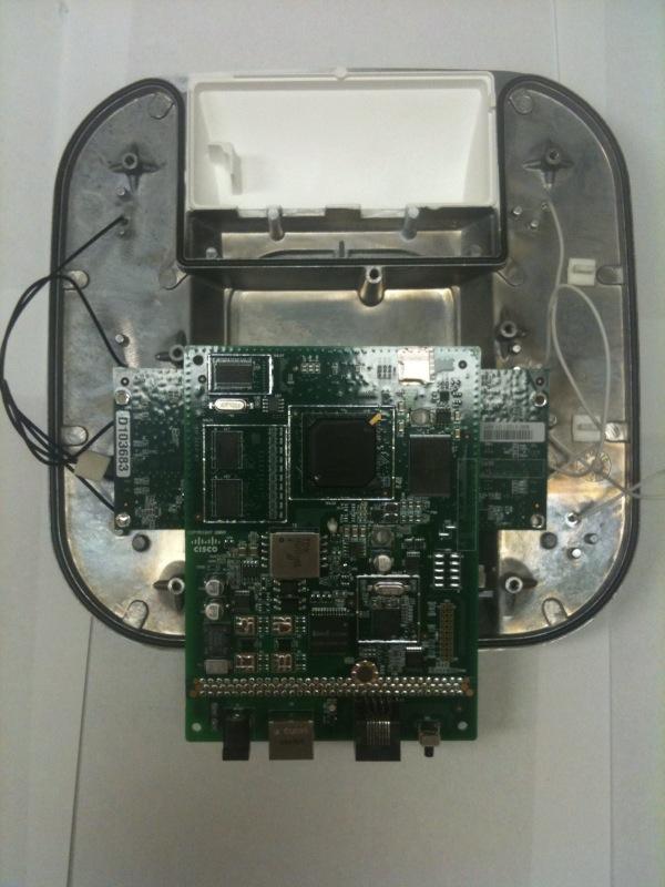
If you have gear to play with you can run various commands and see the (802.1X) process at work. I will highlight a few commands quick for brief overview with a Cisco WLC and Cisco autonomous access point. Debug is your friend and I encourage playing with the debug function.

EXAMPLE #1 - Session Timeout

If you are familiar with the Cisco WLCs . You may have noticed a check box called “Enable Session Timeout”. This feature can be found under WLAN-> (pick your wlan)->ADVANCED -> Session Timeout (check box). Session Timeout is feature set per WLAN setting.

This feature allows you to add a reauthenication timer (or shall we say a rekeying event). Lets say for example you keep the 1800 second timeout value. This means every 1800 seconds from the time your client authenticated to the wireless network the WLC will send a deauthentication frame to the client. Thus causing the client to reauthenticate (or shall we say rekey). 

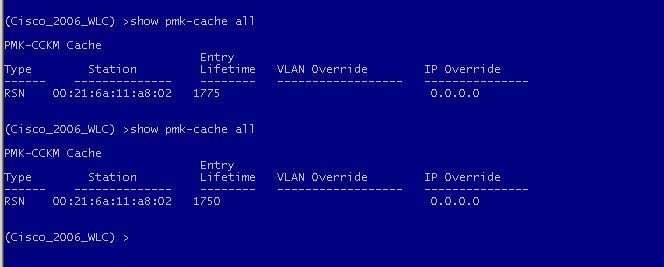
You can also see the clients PMK record in the WLC. Drop into the CLI of the WLC  >show pmk-cache. Under the lifetime value you will see a timer and it counts down. Once it hits zero your client will rekey. This is directly related to the “enable session timeout”

** CAUTION** Some Enterprise environments disable or increase the timeout value to equal 24 hours. Some sensitive applications can be disrupted by frequent re- authentication.

Below is an example:

(Cisco_2006_WLC) >show pmk-cache all

Type        Station         Lifetime   VLAN Override        IP Override

------    --------------    --------   ------------------   ---------------

RSN    00:21:6a:11:a8:02   1775                              0.0.0.0

(Cisco_2006_WLC) >show pmk-cache all

Type        Station         Lifetime   VLAN Override        IP Override

-----    --------------    --------   ------------------   ---------------

RSN    00:21:6a:11:a8:02   1750                              0.0.0.0

Example #2 - Manually Update the GTK on a autonomous access point

Drop into the CLI of the Cisco autonomous access point and issue the following command: 

dot11 dot11Radio 0 update-group-key

ap#dot11 dot11Radio 0 update-group-key

*Mar  2 21:28:05.767: dot11_dot1x_new_key: mcst encrypt mode 0x10 gtk len 32
*Mar  2 21:28:05.767: dot11_dot1x_distribute_bkey: Updating Group Key: vlan=0, index=2, len=32
*Mar  2 21:28:05.767: dot11_dot1x_hex_dump: GTK: 5A CA 2D 68 1C 0E FD A2 DF 6E 8C A4 E6 CE D3 FB 71 F5 6C 84 8C BF EB 35 4C C0 80 CB 3E D1 48 B0
*Mar  2 21:28:05.768: dot11_dot1x_send_ssn_gtk: Sending GTK Message 1 to 0021.6a11.a802
*Mar  2 21:28:05.768: dot11_dot1x_distribute_bkey: Multicast key distributed to 1 clients

Example # 3 - Debug on the Cisco WLC 

There is a host of 802.1x / AAA commands. I deployed dot1x states/event enabled.

(Cisco_2006_WLC) >debug dot1x states enable

(Cisco_2006_WLC) >debug dot1x events enable

Sun Oct  3 11:56:44 2010: d8:30:62:80:61:a1 Processing RSN IE type 48, length 20 for mobile d8:30:62:80:61:a1

!! States 0 PMKIDs. This means this is a new device on the WLC and there is no PMKIDs in que

Sun Oct  3 11:56:44 2010: d8:30:62:80:61:a1 Received RSN IE with 0 PMKIDs from mobile d8:30:62:80:61:a1

!! The WLC moves the client into the connecting state.

Sun Oct  3 11:56:44 2010: d8:30:62:80:61:a1 dot1x - moving mobile d8:30:62:80:61:a1 into Connecting state

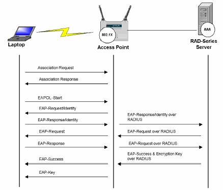
!! The WLC is sending the EAP-Request/Identity

Sun Oct  3 11:56:44 2010: d8:30:62:80:61:a1 Sending EAP-Request/Identity to mobile d8:30:62:80:61:a1 (EAP Id 1)

!! The WLC received an EAP packet from the supplicant

Sun Oct  3 11:56:44 2010: d8:30:62:80:61:a1 Received EAPOL EAPPKT from mobile d8:30:62:80:61:a1

!! The supplicant responded to the Identity Response

Sun Oct  3 11:56:44 2010: d8:30:62:80:61:a1 Received Identity Response (count=1) from mobile d8:30:62:80:61:a1

!! The next state after connecting is authenticating

Sun Oct  3 11:56:44 2010: d8:30:62:80:61:a1 EAP State update from Connecting to Authenticating for mobile d8:30:62:80:61:a1

Sun Oct  3 11:56:44 2010: d8:30:62:80:61:a1 dot1x - moving mobile d8:30:62:80:61:a1 into Authenticating state

!! This I understand means the WLC is sending the response to the AAA server

!! “Entering Backend Auth Response state for mobile”

Sun Oct  3 11:56:44 2010: d8:30:62:80:61:a1 Entering Backend Auth Response state for mobile d8:30:62:80:61:a1

!! EAP PROCESS

Sun Oct  3 11:56:44 2010: d8:30:62:80:61:a1 Processing Access-Challenge for mobile d8:30:62:80:61:a1

Sun Oct  3 11:56:44 2010: d8:30:62:80:61:a1 Entering Backend Auth Req state (id=112) for mobile d8:30:62:80:61:a1

Sun Oct  3 11:56:44 2010: d8:30:62:80:61:a1 WARNING: updated EAP-Identifer 1 ===> 112 for STA d8:30:62:80:61:a1

!! The authentication server (AAA) is sending the EAP request through the WLC

Sun Oct  3 11:56:44 2010: d8:30:62:80:61:a1 Sending EAP Request from AAA to mobile d8:30:62:80:61:a1 (EAP Id 112)

!! Response from supplicant

Sun Oct  3 11:56:44 2010: d8:30:62:80:61:a1 Received EAPOL EAPPKT from mobile d8:30:62:80:61:a1

Sun Oct  3 11:56:44 2010: d8:30:62:80:61:a1 Received EAP Response from mobile d8:30:62:80:61:a1 (EAP Id 112, EAP Type 17)

Sun Oct  3 11:56:44 2010: d8:30:62:80:61:a1 Entering Backend Auth Response state for mobile d8:30:62:80:61:a1

!! EAP PROCESS

Sun Oct  3 11:56:44 2010: d8:30:62:80:61:a1 Processing Access-Challenge for mobile d8:30:62:80:61:a1

Sun Oct  3 11:56:44 2010: d8:30:62:80:61:a1 Entering Backend Auth Req state (id=112) for mobile d8:30:62:80:61:a1

Sun Oct  3 11:56:44 2010: d8:30:62:80:61:a1 WARNING: updated EAP-Identifer 112 ===> 112 for STA d8:30:62:80:61:a1

!! AAA request from server to supplicant

Sun Oct  3 11:56:44 2010: d8:30:62:80:61:a1 Sending EAP Request from AAA to mobile d8:30:62:80:61:a1 (EAP Id 112)

Sun Oct  3 11:56:44 2010: d8:30:62:80:61:a1 Received EAPOL EAPPKT from mobile d8:30:62:80:61:a1

Sun Oct  3 11:56:44 2010: d8:30:62:80:61:a1 Received LEAP EAP Request (type=17, ver=1) from mobile d8:30:62:80:61:a1

Sun Oct  3 11:56:44 2010: d8:30:62:80:61:a1 Entering Backend Auth Response state for mobile d8:30:62:80:61:a1

Sun Oct  3 11:56:44 2010: d8:30:62:80:61:a1 Processing Access-Accept for mobile d8:30:62:80:61:a1

!! Here is the enable session we talked about. It is set @ 1800 seconds

Sun Oct  3 11:56:44 2010: d8:30:62:80:61:a1 Setting re-auth timeout to 1800 seconds, got from WLAN config.

Sun Oct  3 11:56:44 2010: d8:30:62:80:61:a1 Station d8:30:62:80:61:a1 setting dot1x reauth timeout = 1800

Sun Oct  3 11:56:44 2010: d8:30:62:80:61:a1 Creating a PKC PMKID Cache entry for station d8:30:62:80:61:a1 (RSN 2)

!! Access point adds PMKID cache for supplicant

Sun Oct  3 11:56:44 2010: d8:30:62:80:61:a1 Adding BSSID 00:1c:b0:06:d2:d5 to PMKID cache for station d8:30:62:80:61:a1

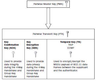
!! This is the PMK that was derived

Sun Oct  3 11:56:44 2010: New PMKID: (16)

Sun Oct  3 11:56:44 2010:      [0000] 02 4a 48 af f6 d6 32 8f 2b 1f ee cc 5a 0a 58 12

Sun Oct  3 11:56:44 2010: d8:30:62:80:61:a1 Disabling re-auth since PMK lifetime can take care of same.

Sun Oct  3 11:56:44 2010: Including PMKID in M1  (16)

Sun Oct  3 11:56:44 2010:      [0000] 02 4a 48 af f6 d6 32 8f 2b 1f ee cc 5a 0a 58 12

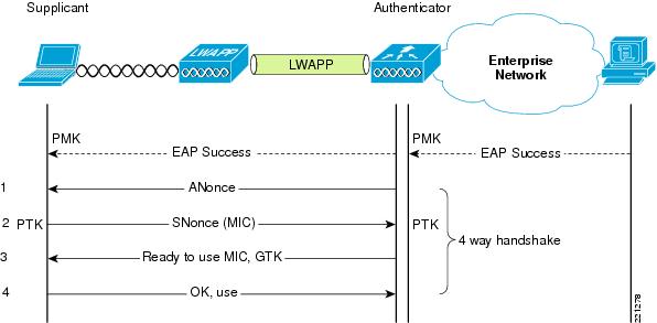
!! Message 1 – This is our first exchange in the 4 way handshake. This is where the authenticator sends the ANonce and mac address.

Sun Oct  3 11:56:44 2010: d8:30:62:80:61:a1 Sending EAPOL-Key Message to mobile d8:30:62:80:61:a1

 state INITPMK (message 1), replay counter 00.00.00.00.00.00.00.00

Sun Oct  3 11:56:44 2010: d8:30:62:80:61:a1 Entering Backend Auth Success state (id=112) for mobile d8:30:62:80:61:a1

Sun Oct  3 11:56:44 2010: d8:30:62:80:61:a1 Received Auth Success while in Authenticating state for mobile d8:30:62:80:61:a1

Sun Oct  3 11:56:44 2010: d8:30:62:80:61:a1 dot1x - moving mobile d8:30:62:80:61:a1 into Authenticated state

Sun Oct  3 11:56:45 2010: d8:30:62:80:61:a1 802.1x 'timeoutEvt' Timer expired for station d8:30:62:80:61:a1

!! Message received from the supplicant

Sun Oct  3 11:56:45 2010: d8:30:62:80:61:a1 Received EAPOL-Key from mobile d8:30:62:80:61:a1

!! Message 2 – This is our second exchange in the 4 way handshake. This client is send the SNonce and the supplicant mac address.

Sun Oct  3 11:56:45 2010: d8:30:62:80:61:a1 Received EAPOL-key in PKT_START state (message 2) from mobile d8:30:62:80:61:a1

Sun Oct  3 11:56:45 2010: d8:30:62:80:61:a1 Stopping retransmission timer for mobile d8:30:62:80:61:a1

!! Message 3 – This is our third exchange in the 4 way handshake. This is where the GTK is being derived and sent back at the supplicant.

Sun Oct  3 11:56:45 2010: d8:30:62:80:61:a1 Sending EAPOL-Key Message to mobile d8:30:62:80:61:a1

state PTKINITNEGOTIATING (message 3), replay counter 00.00.00.00.00.00.00.02


Sun Oct  3 11:56:45 2010: d8:30:62:80:61:a1 Received EAPOL-Key from mobile d8:30:62:80:61:a1


!! Message 4 – This is our fourth exchange in the 4 way handshake. This is confirmation the keys were installed.

Sun Oct  3 11:56:45 2010: d8:30:62:80:61:a1 Received EAPOL-key in PTKINITNEGOTIATING state (message 4) from mobile d8:30:62:80:61:a1

Sun Oct  3 11:56:45 2010: d8:30:62:80:61:a1 Stopping retransmission timer for mobile d8:30:62:80:61:a1

Sun Oct  3 11:57:40 2010: d8:30:62:80:61:a1 Sending EAPOL-Key Message to mobile d8:30:62:80:61:a1

state PTKINITDONE (message 5 - group), replay counter 00.00.00.00.00.00.00.03

!! Message 5 – Is our group key update

!! You can see here it states updated broadcast key and it was sent to the supplicant

Sun Oct  3 11:57:40 2010: d8:30:62:80:61:a1 Updated broadcast key sent to mobile D8:30:62:80:61:A1

!! Group key timer is set @ 3653 seconds. At which point the group key will be re-keyed.

Sun Oct  3 11:57:40 2010: 00:1c:b0:06:d2:d0 Resetting the group key timer for 3653 seconds on AP 00:1c:b0:06:d2:d0(0)

Sun Oct  3 11:57:40 2010: d8:30:62:80:61:a1 Received EAPOL-Key from mobile d8:30:62:80:61:a1

!! Message 6 – This is confirmation the from the supplicant

Sun Oct  3 11:57:40 2010: d8:30:62:80:61:a1 Received EAPOL-key in REKEYNEGOTIATING state (message 6) from mobile d8:30:62:80:61:a1

Sun Oct  3 11:57:40 2010: d8:30:62:80:61:a1 Stopping retransmission timer for mobile d8:30:62:80:61:a1


Play with the debugs ... ENJOY!


Sunday
Oct032010

GEORGE STEFANICK - CWSP JOURNEY, (CHAPTER 5 – 4- WAY HANDSHAKE POST#5)- 10/03/2010

GEORGE STEFANICK - CWSP JOURNEY, (CHAPTER 5 – 4 WAY HANDSHAKE POST#5)- 10/03/2010

The 4-way handshake is a unique process and thus why I think it is important to cover in detail. But first lets recap.

We’ve learned  the MSK (Master Session Key)  is used for seeding material in the creation of the PMK (Pairwise Master Key) . The PMK (Pairwise Master Key) and GMK (Group Master Key)  are then seeding material for the PTK (Pairwise Transient Key) and GTK (Group Temporal Key).

The MSK and PMK are negotiated between the supplicant and the authentication server (AAA). Once created, these keys are then moved to the authenticator (access point) via a Radius packet.

In contrast, PTK (Pairwise Transient Key) is derived differently. It is derived between the supplicant and the authenticator (access point). The authentication server (AAA), at this stage, has completed it’s task and is out of the mix.

Since the supplicant and the authenticator have mutual information about each other (PMK) key . They both can derive their unique Temporal keys in a process called the “4-way handshake” .

The purpose of the 4-way handshake is to derive a unique PTK key that will be used to encrypt client unicast traffic between this station and the access point.  This key is unique. No two stations on an access point will have identical PTK keys.

So lets get started …

After a successful EAP authentication the 4-way handshake begins. Note, as I mentioned before, this is now between the supplicant and the authenticator. 

The 4-way handshake shares very unique and random information between the supplicant and the access point to derive the PTK key. There is something called PRF (pseudo-random function). It uses a combination of “randomness”, as I like to call it.

It includes the PMK+ Supplicant Mac Address + Authenticator Mac Address + random Nonces) Here is the formula, it can be found on page 199 of the CWSP.

It’s a great visual …

PTK = PRF (PMK + ANonce + SNonce + AA + SPA )

Here are the definitions for reference:

PRF (pseudo-random function) -  A collection of efficiently-computable functions which emulate a random oracle in the following way: no efficient algorithm can distinguish (with significant advantage) between a function chosen randomly from the PRF family and a random oracle (a function whose outputs are fixed completely at random). Pseudorandom functions are vital tools in the construction of cryptographic primitives, especially secure encryption schemes.

Nonce - is an abbreviation of number used once (it is similar in spirit to a nonce word). It is often a random or pseudo-random number issued in an authentication protocol to ensure that old communications cannot be reused in replay attacks.

ANonce – A authenticator nonce

SNonce – A supplicant nonce

AA – Authenticators Mac Address (access point)

SPA – Supplicants Mac Address (wireless client)


The 4-way handshake looks like a simple 4-way frame exchange. But inside these frames “random” magic is happening before your very eyes. Below is a breakdown of each exchange:

4-way handshake message 1

In the first message, the authenticator sends the supplicant a nonce. This is referred to as the ANonce. Along with this ANonce, the frame includes the authenticators mac address. At this point the supplicant has all the goods to create the PTK. It has the Anonce, authenticators mac address as well as its own Snonce and mac address, of itself.

4-way handshake message 2

The supplicant creates its nonce. This is referred to as the SNonce. The supplicant can now calculate the PTK because it has all the goods from the first handshake. In the second message, the supplicant sends the SNonce to the authenticator. The supplicant also sends the security parameters (RSN) information. The entire message gets an authentication check using the (KCK/MIC) from the pairwise key hierarchy. The authenticator can then verify that the information, including the security parameters sent at association are valid.

4-way handshake message 3 

In the third message the authenticator derives the GTK key from the GMK key. The authenticator derives an ANonce, RSN information element info and a MIC. This information is then sent to the supplicant in a EAPOL-Key frame. This is kept  secret  from sniffing, because it is encrypted within the PTK.  

4-way handshake message 4 

The fourth message acts as a confirmation. It indicates that the temporal keys are installed.


The PTK is comprised into three keys which is important to know, I like to call them the “internal PTK” keys. These KCK, KEK, and TK component. These keys secure the 4-way handshake (KCK), provide data integrity during the 4-way handshake (KCK) and provide encryption used to encrypt and decrypt the MSDU payload of 802.11 data frames between the station and the access point.  

Key Confirmation Key (KCK) - The first key is the EAPOL-key confirmation key (KCK). The KCK is used by the EAPOL-key exchanges to provided data origin authenticity.

Key Encryption Key (KEK) - The second key is the EAPOL-key encryption key (KEK). The KEK is used by the EAPOL-key exchanges to provide for confidentiality.

Temporal Key (TK) - The third key is the temporal key, which is used by the data-confidentiality protocols (TKIP/CCMP)


Thursday
Sep092010

GEORGE STEFANICK - CWSP JOURNEY, (CHAPTER 5 – KEYS POST#4)- 9/10/2010


GEORGE STEFANICK - CWSP JOURNEY, (CHAPTER 5 – KEYS POST#4)- 9/10/2010

First, this is a lot of information and it is very detailed at that. I encourage further reading and study for a complete step by step explanation. These are my notes for reference. I hope you find them useful. 

If you are new to wireless security especially 802.11i, one could be intimidated by all of these KEYS. I can remember thinking to myself, “Why in gods name is there so many keys and they do what again!?”

I would encourage you to read Chapter 5 of the official CWSP study guide, Devin’s ‘chicken egg’ white  paper and the 802.11 Wireless Networks ‘Definitive Guide 2nd edition’ for a full explanation.

To simplify, I would like to reference fig 5.18 on page 194 of the CWSP study guide. The pyramid offers a great visual as to the RSN Key Hierarchy process.  Let’s break down each LAYER.


“Master Session Key - MSK”

The MSK is sometimes called the ‘AAA key’. The MSK is on top of the food chain and will provide “seeding  / keying material” for the PMK (Pairwise Master Key). MSKs are created during the 802.1X/EAP process.

802.1X/EAP –  The MSK is derived at the supplicant and the authentication server (AAA) during the EAP authentication process. The supplicant and the authentication server (AAA) will know information about each other during the “mutual” authentication exchange of credentials. I added a GREAT Peap Choreography at the end of this post.

(this is all black magic and is outside of the scope of the exam)

What is important to remember is that both the supplicant and authentication server (AAA) have both derived identical  MSK keys during this mutual authentication process which will later be used as seeding material for PMKs.

PSK -  In the case where PSK is used, whereby putting a static PSK key on a station and access point  there is no MSK keying material because there is no authentication server (AAA) in use to derive a MSK. So your PSK is your PMK.


Additional reading material

<
RFC4017 states>
Master Session Key (MSK) Keying material that is derived between the EAP peer and server and exported by the EAP
method. The MSK is at least 64 octets in length. In existing implementations, an AAA server acting as an EAP server
transports the MSK to the authenticator.

<802.11 2007 states:>
3.80 master session key (MSK): Keying material that is derived between the Extensible Authentication Protocol (EAP) peer and
exported by the EAP method to the Authentication Server (AS). This key is at least 64 octets in length.

“Master Key Layer”

Next layer down on the food chain is the “Master Key Layer”. This is where your PMK (Pairwise Master Key) and GMK (Group Master Key) will be derived! 

PMK  (Pairwise Master Key)

The purpose of the PMK is to create seeding material for the PTK (pairewise transient key)

The PMK is derived by the station and authentication server (AAA). The PMK shall be computed as the first 256 bits (bits 0–255) of the MSK. Since the station and the authentication server (AAA) both have the same MSK, because of the 802.1X/EAP process, the PMKs derived will be identical.

The PMK that is derived at the authentication server (AAA) is sent to the authenticator. Once this occurs the station and authenticator  both have identical PMKs. The PMK is unique between the station and the authenticator. No other station will have identical PMKs. A new PMK is generated when a station authenticates or re-authenticates . PMKs are also used in ‘fast’ roaming, whereby a client can negate a full 802.1X authentication. More about that in a future blog post. Again, keep in mind that the PMK is used as seeding material to create the PTK. 

PSK -   In the case where you use a PSK (PreShare Key)  on a station and access point the Master Keys are derived by using a passphrase-to-PSK mapping.   So your PSK is your PMK key. 

Additional reading material

< IEEE Std 802.11 - 2007>
3.97 pairwise master key (PMK): The highest order key used within this standard. The PMK may be derived from a key generated by an Extensible Authentication Protocol (EAP) method or may be obtained directly from a preshared key (PSK).


< IEEE Std 802.11 - 2007>
The PTK shall not be used longer than the PMK lifetime as determined by the minimum of the PMK lifetime indicated by the AS, e.g., Session-Timeout + dot1xAuthTxPeriod or from the
dot11RSNAConfigPMKLifetime MIB variable. When RADIUS is used and the Session-Timeout attribute is not in the RADIUS Accept message, and if the key lifetime is not otherwise specified, then the PMK lifetime is infinite.


< IEEE Std 802.11 - 2007>
When not using a PSK, the PMK is derived from the MSK. The PMK shall be computed as the first 256 bits (bits 0–255) of the MSK: PMK L(MSK, 0, 256). When this derivation is used, the MSK must consist of at least 256 bits

< IEEE Std 802.11 - 2007> 5.8.2.2 Operations with PSK

The following AKM operations are carried out when the PMK is a PSK:
— A STA discovers the AP’s security policy through passively monitoring Beacon frames or through active probing (shown in Figure 5-11). A STA associates with an AP and negotiates a security
policy. The PMK is the PSK.

— The 4-Way Handshake using EAPOL-Key frames is used, just as with IEEE 802.1X authentication,
when an AS is present. See Figure 5-13.

— The GTK and GTK sequence number are sent from the Authenticator to the Supplicant just as in the
AS case. See Figure 5-13 and Figure 5-14.


GMK  (Group Master Key)

The GMK is randomly created by the authenticator. The purpose of the GMK is to create “seeding material” for the GTK. The GMK lives on the authenticator ONLY. Each authenticator will have it’s own unique GMK. Some vendors allow you to change the GMK dynamically.  I will share more on this in a future blog post.


“Temporal Key Layer”

In the temporal key layer we will discuss two keys. The PTK (Pairwise Transient Key) and  GTK (Group Temporal Key). Both have very unique tasks …. The temporal keys are derived via the 4-Way Handshake process.

PTK (Pairwise Transient Key)

The propose of the PTK keys is to encrypt unicast traffic between the station and access point. The PTK is a unique encryption key and no other station will have the same identical PTK key.

The PTK is composed of 3 parts"

Key Confirmation Key (KCK), Key Encryption Key (KEK), Temporal Key (TK)

GTK  (Group Temporal Key)

The purpose of the GTK key is to encrypt broadcast and multicast traffic between the client(s) and access point (BSS). ALL THE CLIENTS on the same BSS will share identical GTK keys.  That right, multicast and broadcast traffic are keyed separate from the unicast traffic. Keeping in mind this is WHY when using a transitional network, your lowest encryption type is used for your GTK key.

You may have heard about the recent buzz in the industry around “hole 196”. This was based on the exploitation of the GTK key. 

An important part of the PTK and GTK is the 4-way handshake. My next post will cover this in detail ..

 Great image of the frame exchange process

Wednesday
Sep082010

WLC: TACACS+ Config Note! 


Quick note about Cisco WLC and TACACS+. Got a call from a colleague who spent 2 hours on this issue. It is his first WLC install. 

When you configure Cisco TACACS+ on a Cisco WLC you need to add your TACACS+ server IP and secret information in 2 sections (authentication and authorization).  This is required for TACACS+ to work on a WLC.

 First you need to be authenticated and then authorized whereby you receive your (role). 

*The accounting section is not required for TACACS+ to work 

If you fail to enter only one section or not at all and run a debug “aaa tacacs enable” you will see: 

(WiSM-slot1-2) >debug aaa tacacs enable
(WiSM-slot1-2) >*Sep 06 15:02:25.495: tplusServerStateSet(), index=1 state=1
*Sep 06 15:17:13.343: Forwarding request to 10.10.10.100 port=49
*Sep 06 15:17:15.157: tplus response: seq_no=2 session_id=f058fe68 length=16 encrypted=0
*Sep 06 15:17:15.157: TPLUS_AUTHEN_STATUS_GETPASS
*Sep 06 15:17:15.157: auth_cont get_pass reply: pkt_length=25
*Sep 06 15:17:15.157: processTplusAuthResponse: Continue auth transaction
*Sep 06 15:17:15.171: tplus response: seq_no=4 session_id=f058fe68 length=6 encrypted=0
*Sep 06 15:17:15.172: tplus_make_author_request: athr server not found


Configure TACACS+ on WLC 

Use these commands to configure a TACACS+ authentication server:

config tacacs auth add index server_ip_address port# {ascii | hex} shared_secret—Adds a TACACS+ authentication server.

config tacacs auth delete index—Deletes a previously added TACACS+ authentication server.

config tacacs auth (enable | disable} index—Enables or disables a TACACS+ authentication server.

config tacacs auth server-timeout index timeout—Configures the retransmission timeout value for a TACACS+ authentication server.

Use these commands to configure a TACACS+ authorization server:

config tacacs athr add index server_ip_address port# {ascii | hex} shared_secret—Adds a TACACS+ authorization server.

config tacacs athr delete index—Deletes a previously added TACACS+ authorization server.

config tacacs athr (enable | disable} index—Enables or disables a TACACS+ authorization server.

config tacacs athr server-timeout index timeout—Configures the retransmission timeout value for a TACACS+ authorization server.

Use these commands to configure a TACACS+ accounting server:

config tacacs acct add index server_ip_address port# {ascii | hex} shared_secret—Adds a TACACS+ accounting server.

config tacacs acct delete index—Deletes a previously added TACACS+ accounting server.

config tacacs acct (enable | disable} index—Enables or disables a TACACS+ accounting server.

config tacacs acct server-timeout index timeout—Configures the retransmission timeout value for a TACACS+ accounting server. 

Use these commands to see TACACS+ statistics:

show tacacs summary—Shows a summary of TACACS+ servers and statistics.

show tacacs auth stats—Shows the TACACS+ authentication server statistics.

show tacacs athr stats—Shows the TACACS+ authorization server statistics.

show tacacs acct stats—Shows the TACACS+ accounting server statistics.


Page 1 ... 7 8 9 10 11 ... 17 Next 20 Entries »